A powered, upper body exoskeleton developed by students at the University of Pennsylvania.

More Cable Testing

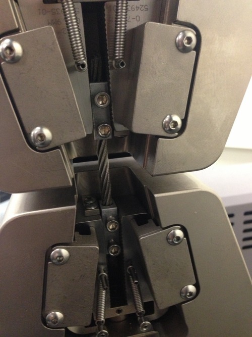
Based on the last testing, our team developed grips that were more accurate to the forces that the cables would be experiencing.  Two set screws were used to grip down on the cable – two of these blocks were used to hold the cable in between the grips of the machine.

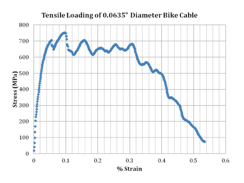
The given testing gave more reasonable results, though slipping of the cable is clear in the stress vs. strain curve below.

image

image

Bike Brake Cable Testing

The team performed analysis on two types of bike brake cables in order to determine their stress strain curves using an MTS materials testing machine.  We’ll be continuing testing with the 0.064" diameter, as it withstood almost 300 lbf, and we’ll be expecting loads of 180 lbf in the suit.

These tests were conducted by simply gripping the bike cables in the MTS machine.  However, the given yield strengths are less than predicted – by gripping on the actual cable, there is increased stress at these points.  Further testing will be done with a gripping style setup, possibly by using set screw attachments.

image

image

DC Motor + Cable Drive

Based on our actuation selection, a cable drive will be implemented on the exoskeleton to transmit the power from the motor to the elbow joint.  A cable drive system allows for non-localized actuation.  Other exoskeletons, such as HAL (image below), use localized motors for actuation.  With non-localized actuation, it is possible to increase the motor strength and decrease the weight at the joint extremities.

We’ll be investigating cables and sheathing to transmit the force from the back to the elbow joint.

image